Contact us

7 Best Stator Testers for Motor Testing

Choosing the right Stator tester can prevent costly motor failures, unexpected downtime, and repeated rewinding work. A reliable tester helps technicians inspect insulation, winding balance, resistance, and possible short circuits before problems become severe.

This guide examines seven leading stator testers for motor testing. Each option is considered through practical testing needs, measurement accuracy, operating range, portability, and user feedback. Features matter, but field conditions matter more. A tester that performs well in a clean laboratory may feel limited beside an oily repair bench.

Real technicians need clear readings. They also need durable leads, simple controls, dependable calibration, and useful reports. Small details count. A bright display helps in poor workshop lighting. Strong test clamps reduce connection errors. Safe discharge functions protect both equipment and operators.

The comparison reflects established motor-testing practices and manufacturer specifications, while recognizing that product performance can vary by model and application. No tester is perfect. Some devices offer advanced diagnostics but require training. Others are affordable and practical, yet provide fewer analytical details. That trade-off deserves honest attention.

Before selecting a unit, consider motor voltage, winding type, testing frequency, service environment, and staff experience. Do not rely on one reading alone. Confirm unusual results with visual inspection and additional electrical tests. A tester supports professional judgment; it does not replace it.

These seven options provide a useful starting point for maintenance teams, repair shops, and industrial electricians. The best choice is the one that delivers repeatable results under your actual working conditions. Sometimes, practical simplicity wins.
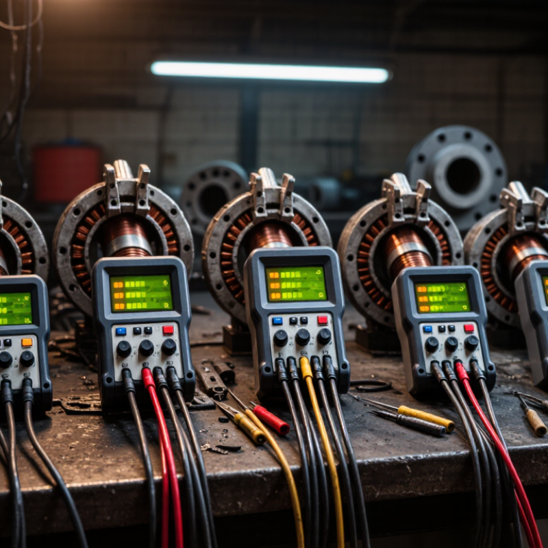
7 Best Stator Testers for Motor Testing

Stator Testing Fundamentals and Key Diagnostic Functions

A stator tester checks whether motor windings can create balanced magnetic fields safely. Testing begins with a clean, isolated motor and accurate winding data. Measure resistance between each phase and record the temperature. Copper resistance changes as temperature rises. A small phase difference may indicate loose connections, damaged conductors, or uneven winding length.

The result is not always obvious.

The seven most useful tester categories cover different faults: winding resistance, low-resistance measurement, inductance, surge comparison, insulation resistance, dielectric withstand, and multifunction analysis. Resistance testing finds open circuits and phase imbalance. Inductance testing can reveal shorted turns that resistance testing misses. Surge testing applies a controlled pulse and compares waveform patterns between windings.

Look closely. A distorted waveform deserves investigation.

Insulation resistance testing checks leakage between windings and the stator core. Dielectric testing applies higher voltage under controlled conditions, so trained personnel and approved procedures are essential. A multifunction analyzer saves time, but it cannot replace sound judgment. Select a tester with adjustable voltage, temperature compensation, clear data storage, and traceable calibration. Keep test leads short and inspect their insulation before use. I have seen clean readings caused by poor contact pressure. Repeat doubtful measurements with the same setup. Trends across repairs often matter more than one perfect number.

How to Choose a Stator Tester for Different Motor Types

7 Best Stator Testers for Motor Testing

Choosing a stator tester starts with the motor, not the instrument. Small single-phase motors need accurate winding resistance and capacitance checks. Three-phase induction motors require phase balance, insulation resistance, and surge testing. Large industrial motors need higher test voltage, stronger data logging, and safer discharge control.

Seven useful tester types cover most applications: winding resistance meters, insulation resistance testers, high-potential testers, surge testers, inductance meters, phase-balance analyzers, and core-loss testers. Resistance meters reveal loose joints and unequal coils. Insulation testers detect moisture or aging materials. High-potential testing checks dielectric strength, but only when the motor’s limits are known. Surge testing can expose turn-to-turn faults that ordinary resistance measurements miss.

I have found that portability matters in repair workshops. A heavy unit may offer excellent readings but remain unused on a crowded service cart. For small motors, a compact tester with simple lead connections is often practical. Medium-voltage motors need guarded terminals, controlled ramping, and clear discharge warnings. Motors with variable-speed drives can produce confusing results if cables remain connected, so isolation is essential.

Do not choose the highest voltage automatically. It may damage an old winding. Calibration records, repeatable readings, and traceable test procedures support reliable decisions. Some meters display impressive graphs, yet operators may misunderstand them. Training still matters. My own early mistake was treating balanced resistance as proof of a healthy stator. It was not. A motor can pass that check and still have weak insulation or shorted turns.

Seven Stator Tester Categories and Their Main Applications

7 Best Stator Testers for Motor Testing

Seven Stator Tester Categories and Their Main Applications

Stator testing begins with the failure mode, not the instrument. The seven main categories are insulation resistance, polarization index, high-potential, surge comparison, winding resistance, inductance, and core-loss testers. Insulation resistance testers reveal moisture and contamination between windings and ground. Polarization index testing adds time-based evidence. High-potential testing checks dielectric strength, but careless voltage selection can damage aged insulation.

Surge testers identify turn-to-turn weaknesses that ordinary resistance measurements may miss. Winding-resistance testers expose loose joints, broken conductors, and phase imbalance. Inductance testers help compare coil geometry and magnetic symmetry during production. Core-loss testers locate localized heating in damaged laminations. Small details matter. A warm terminal can distort readings. The operator should record winding temperature, test voltage, lead arrangement, and stabilization time.

The International Energy Agency reports that electric motor systems consume roughly 45% of global electricity, making reliable diagnostics economically significant. The U.S. Department of Energy also identifies motor systems as a major industrial energy load. These figures support condition-based testing, especially where unplanned downtime affects pumps, compressors, and production lines. IEC 60034 and IEEE test guidance improve repeatability, yet field results remain imperfect. Surface leakage, poor grounding, and inconsistent probe pressure can create false confidence. A tester is only as reliable as its method.

7 Best Stator Testers for Motor Testing - Seven Stator Tester Categories and Their Main Applications

Stator Tester Category Primary Test Principle Main Measurements Typical Motor Types Main Applications Key Advantages Important Limitations
Winding Resistance Tester Applies a controlled direct current and measures the voltage drop across each winding. Phase-to-phase resistance, resistance imbalance, winding continuity, and temperature-corrected resistance. Three-phase induction motors, synchronous motors, brushless motors, and transformer-fed windings. Incoming inspection, production testing, repair verification, and detection of loose joints or broken conductors. Simple, repeatable, and effective for identifying high-resistance connections and phase imbalance. Does not reliably detect insulation weakness or turn-to-turn faults that have similar DC resistance.
Insulation Resistance Tester Applies a high DC test voltage between windings and ground, then measures leakage current. Insulation resistance, polarization index, dielectric absorption ratio, and leakage current. Low- and medium-voltage AC motors, generators, alternators, and large rewound stators. Preventive maintenance, moisture assessment, storage checks, and post-repair insulation evaluation. Quickly reveals contamination, moisture ingress, aging insulation, and ground leakage. Results vary with temperature, humidity, surface cleanliness, and test duration; it is not a complete winding test.
High-Potential Dielectric Tester Raises the voltage above normal operating level to verify the dielectric strength of the insulation system. Withstand voltage, trip current, leakage current, ramp profile, and breakdown indication. Newly manufactured stators, repaired motors, generators, and insulated winding assemblies. Safety compliance, end-of-line quality control, repair-shop acceptance testing, and type testing. Provides a strong pass/fail assessment of insulation withstand capability. Can stress or damage aged insulation; test voltage and procedure must follow applicable safety standards.
Surge Comparison Tester Applies fast-rising voltage pulses and compares the resulting oscillating waveforms between windings or phases. Waveform area, peak voltage, ringing frequency, phase-to-phase deviation, and turn-to-turn fault indicators. AC induction motors, permanent-magnet motors, servo motors, traction motors, and random-wound stators. Production line testing, coil comparison, repair verification, and detection of turn-to-turn insulation defects. Highly sensitive to inter-turn faults that resistance and standard insulation tests may miss. Requires suitable pulse levels, consistent connections, and trained interpretation to avoid false results.
Motor Circuit Analysis Tester Analyzes the electrical response of the complete motor circuit using low-voltage signals and frequency-based measurements. Impedance, inductance, phase angle, resistance, capacitance, and circuit asymmetry. Induction motors, synchronous motors, wound-rotor motors, and motors connected through long cables. Offline maintenance, troubleshooting, baseline trending, and evaluation of rotor, stator, and connection-related abnormalities. Supports condition trending and can identify multiple electrical fault patterns without full disassembly. Diagnosis depends on baseline data, motor design, test setup, and correct separation of cable and motor effects.
Core Loss Tester Energizes the stator core with an alternating magnetic field and measures temperature rise or power loss. Core loss, watts per kilogram, hot-spot temperature, flux distribution, and localized heating. Large AC motors, generators, alternators, and stator cores undergoing rewinding or refurbishment. Repair workshops, rewind quality control, assessment of damaged laminations, and acceptance of refurbished cores. Detects shorted laminations and excessive localized heating that electrical winding tests cannot identify. Requires specialized excitation equipment, thermal monitoring, and careful control of test flux and duration.
Automatic Stator Production Tester Combines several automated electrical tests in a programmed sequence using fixtures, switching, and digital result evaluation. Resistance, inductance, capacitance, insulation resistance, hipot, surge response, and test-time traceability. High-volume stators for household appliances, industrial drives, electric vehicles, pumps, and compact generators. End-of-line manufacturing, automated assembly cells, process control, and statistical quality monitoring. Fast, repeatable, operator-independent testing with automatic pass/fail decisions and production data logging. Higher initial cost, fixture-specific setup, and the need for validated limits for each stator design.

Note: The appropriate test category depends on the motor design, voltage class, production or maintenance environment, applicable safety requirements, and the specific fault types that must be detected.

Step-by-Step Procedures for Accurate Stator Testing

Accurate stator testing begins with a controlled setup. Disconnect the motor completely, isolate stored energy, and confirm zero voltage with a verified meter. Remove dust, oil, and loose connections. Record the nameplate data, winding temperature, and terminal condition. Small details matter.

Use seven tester types for different faults: a digital multimeter, low-resistance ohmmeter, insulation resistance tester, high-voltage withstand tester, surge tester, LCR meter, and growler. Test phase-to-phase resistance with the low-resistance meter, not only a basic multimeter. Compare all readings with the motor’s specifications and with each other. A small imbalance can signal a poor joint or damaged winding. Temperature changes resistance, so note the actual temperature before judging results.

Test insulation from each winding to the frame, then discharge the windings safely. Apply only the voltage and duration specified by the equipment procedure. A surge test can reveal turn-to-turn weaknesses that resistance tests may miss. Use an LCR meter to compare inductance between phases, while a growler can help locate certain localized magnetic faults. I have seen clean readings hide a loose terminal, so inspect connections again. Do not trust one instrument. Repeat doubtful measurements, check lead contact, and record every value. Imperfect data is still useful when its limits are clearly documented.

Safety Practices and Results Interpretation for Motor Testing

Choosing among the 7 best stator testers for motor testing requires more than comparing display features. Safety must guide every measurement. Disconnect the motor, isolate all energy sources, and verify zero voltage with a properly rated meter. Lockout procedures should be followed. Capacitors can retain dangerous energy after shutdown.

Wear suitable eye protection and insulated gloves when required by the site assessment. Inspect test leads for cracked insulation before connecting them. Keep the work area dry and remove loose metal objects. Some testers apply high voltage during insulation or surge tests, so only trained personnel should operate these functions. The motor frame must be properly grounded.

Results need context. Compare phase resistance values, insulation resistance, and surge waveforms against previous records when available. Temperature affects resistance readings, so record the winding and ambient temperatures. A low insulation value may indicate moisture, contamination, aging, or a measurement mistake. Do not condemn a motor from one result.

Trends matter more.

In field testing, I have seen clean resistance readings hide insulation weakness. I have also seen unstable readings caused by poor lead contact. That detail is easy to overlook. Repeat questionable tests, confirm connections, and document the test voltage, duration, temperature, and instrument condition. A tester can reveal evidence, but it cannot replace professional judgment. Results should be reviewed against maintenance history and the motor’s operating environment.