Contact us

How to Choose the Right Electric Furnace Transformer?

Choosing the right Electric Furnace Transformer is a practical engineering decision, not a simple equipment purchase. It affects furnace stability, production quality, energy use, and long-term maintenance costs. A transformer may look suitable on paper, yet perform poorly under repeated thermal cycling or sudden load changes.

This guide explains the main factors professionals review before approving a transformer. These include furnace capacity, primary and secondary voltage, frequency, impedance, phase arrangement, cooling method, and expected duty cycle. Harmonic distortion also deserves attention, especially in installations using thyristor controls or other power-electronic equipment. A transformer room may appear quiet during inspection, while temperature rise tells a different story after several hours of operation.

Site conditions matter. Dust, heat, vibration, limited ventilation, and restricted maintenance access can change the correct specification. Experienced engineers compare manufacturer data with measured operating conditions, rather than relying on nominal ratings alone. They also verify efficiency, insulation class, protection systems, noise levels, and compliance with applicable electrical standards.

No selection method is perfect. Unexpected production changes can expose weaknesses that calculations missed. That is why load records, fault studies, factory test reports, and supplier references should support the final decision. Small details matter. A loose connection, insufficient cooling clearance, or unsuitable tap range can create expensive downtime.

The best transformer balances reliability, performance, safety, and total ownership cost. It should serve the furnace today and remain adaptable tomorrow. This article offers a clear framework for making that choice with greater confidence and fewer costly assumptions.
How to Choose the Right Electric Furnace Transformer?

Understanding the Role and Types of Electric Furnace Transformers

How to Choose the Right Electric Furnace Transformer?

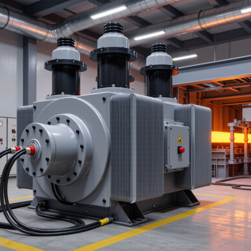
An electric furnace transformer converts incoming voltage into the lower voltage and higher current required by the furnace. Its role is not simply to supply power. It must also handle frequent starts, thermal stress, voltage fluctuations, and sudden load changes. That matters.

Arc furnace transformers serve melting systems that draw intense, unstable current through electrodes. They usually require strong short-circuit performance, robust cooling, and adjustable voltage control. Induction furnace transformers support coil-based heating, where stable output and high current help maintain efficient electromagnetic heating. Resistance furnace transformers are often selected for steadier heating loads, but their insulation and temperature ratings still need careful review.

Common construction choices include oil-immersed and dry-type transformers. Oil-immersed units can manage heavy loads and outdoor conditions effectively when maintenance is properly controlled. Dry-type units may suit indoor installations where fire protection and cleaner operation are priorities. The correct choice depends on furnace capacity, duty cycle, voltage range, installation space, and local safety requirements.

Engineers should examine harmonics, inrush current, cooling capacity, impedance, and tap-changer performance before approving a design. A transformer that matches the furnace’s rated power may still perform poorly during peak cycles. Field measurements are valuable, especially when the furnace operates near its limits. The calculation is rarely perfect. Ambient temperature, cable length, and future production changes can alter the result. Reliable selection combines manufacturer data, site conditions, protection studies, and practical operating records.

Matching Transformer Capacity to Furnace Power Requirements

Choosing an electric furnace transformer starts with real furnace demand, not the nameplate alone. A 500 kW furnace operating at a 0.85 power factor requires about 588 kVA. The calculation is simple. The operating pattern is not.

Review peak load, startup current, duty cycle, and future production changes. Resistance furnaces may operate near unity power factor, while induction equipment can require more reactive power and create significant harmonics. IEEE 519-2022 provides harmonic-control guidance for power systems, so transformer sizing should include harmonic heating and possible derating. A practical design often adds 15% to 25% capacity above calculated demand. However, that margin is not automatically safe. A furnace with frequent cycling may need a larger allowance than a steady-load furnace.

Transformer voltage and secondary current must also match the furnace controller and supply arrangement. For example, a 750 kVA transformer at 480 V delivers approximately 903 A on the secondary side. That current affects conductors, switchgear, cooling, and protection settings.

The U.S. Department of Energy estimates that distribution transformers consume about 61 billion kWh annually in the United States, showing why efficiency deserves attention during selection. IEC 60076-1 also emphasizes correct rating and service conditions. A spreadsheet can still lie. Field temperature, ventilation, harmonic distortion, and short high-load cycles should be checked before approval. Oversizing wastes capital; undersizing causes voltage sag, overheating, and unstable furnace control.

Checking Voltage, Phase, Frequency, and Electrical Compatibility

How to Choose the Right Electric Furnace Transformer?

Checking Voltage, Phase, Frequency, and Electrical Compatibility

Begin with the furnace nameplate and the building’s measured supply. Do not rely only on old drawings. A transformer may accept 480 volts, while the available service provides 460 volts. That difference can affect heating output, controls, and transformer life.

Confirm the primary and secondary voltages separately. Then check whether the system is single-phase or three-phase. The transformer phase must match the furnace load and incoming service. Frequency matters, too. A 50 Hz transformer may not operate correctly on a 60 Hz system. Small control transformers can be especially sensitive.

Measure it carefully.

Electrical compatibility also includes kVA capacity, impedance, grounding, conductor size, and overcurrent protection. Calculate the furnace’s continuous load and allow suitable capacity for startup demand. Heating elements can create a noticeable current surge when energized. The control circuit may also require a different voltage from the heating circuit.

A practical inspection should compare the nameplate, wiring diagram, breaker rating, and actual field measurements. In one common oversight, installers check voltage but ignore phase rotation or neutral requirements. That can delay commissioning. I would also verify terminal tightness and insulation condition, because a correct transformer still fails with poor connections. Local electrical rules and a qualified electrician’s review remain essential before energizing the equipment.

How to Choose the Right Electric Furnace Transformer? - Checking Voltage, Phase, Frequency, and Electrical Compatibility

Selection Dimension What to Check Typical Furnace Requirement Transformer Specification Compatibility Indicator Important Engineering Note
Primary Voltage Measure or confirm the available supply voltage at the installation point. Common industrial supplies include 208 V, 230/240 V, 380 V, 400 V, 415 V, and 480 V. Primary voltage rating must match the actual supply voltage or provide an approved tap arrangement. Acceptable: supply voltage is within the transformer nameplate tolerance. Do not assume that a 230 V-rated transformer is suitable for every 208 V system without checking the nameplate and taps.
Secondary Voltage Identify the furnace heater, control, fan, and auxiliary circuit voltage requirements. Heating elements may use 120 V, 208 V, 240 V, 380 V, or 480 V; controls may require a separate lower voltage. Secondary voltage must equal the furnace-rated voltage under the expected load. Acceptable: secondary voltage matches the heater and control-circuit ratings. An incorrect secondary voltage can cause overheating, low heat output, contactor malfunction, or premature element failure.
Voltage Ratio Compare the required primary-to-secondary voltage relationship. Example: a 480 V supply feeding a 240 V furnace requires an approximate 2:1 ratio. Voltage ratio = Primary voltage ÷ Secondary voltage Example: 480 ÷ 240 = 2.00 Account for voltage taps and expected voltage drop when selecting the final ratio.
Phase Confirm whether the supply and furnace are single-phase or three-phase. Small furnaces may be single-phase; larger heating systems commonly use three-phase power for balanced loading. The transformer phase must match the furnace power circuit unless an engineered phase-conversion arrangement is used. Single-phase load requires a single-phase transformer; three-phase load requires a three-phase transformer. A three-phase furnace should not be supplied from a single-phase transformer without a specifically designed system.
Frequency Verify the utility frequency and the frequency shown on the furnace and transformer nameplates. Most systems operate at 50 Hz or 60 Hz. Transformer frequency rating must be equal to the system frequency. 50 Hz system with a 50 Hz-rated transformer, or 60 Hz system with a 60 Hz-rated transformer. A 60 Hz transformer may not be suitable for 50 Hz operation unless the manufacturer explicitly permits it; lower frequency can increase core flux and heating.
Load Power Add the rated power of heating elements, fans, contactors, controls, and other transformer-fed equipment. Example: 24 kW of furnace heaters plus 1.5 kW of fans and controls equals 25.5 kW total connected load. Use the calculated apparent power in kVA rather than only the heater kW rating. For unity power factor: kVA ≈ kW Motors, electronic controls, and variable-frequency drives may require additional allowance for power factor and harmonics.
Transformer Capacity Compare the calculated load with the transformer continuous kVA rating. Furnace heating may operate for long periods and should be treated as a continuous or high-duty load where applicable. Select a rating above the calculated demand, commonly the next suitable standard size. Example: 25.5 kVA calculated load may require a 30 kVA or larger transformer after design review. Follow applicable electrical codes, local rules, and the equipment manufacturer’s duty-cycle instructions.
Full-Load Current Calculate primary and secondary current for conductors, disconnects, and overcurrent protection. Current depends on voltage, kVA, phase, and power factor. 1-phase: I = kVA × 1000 ÷ V
3-phase: I = kVA × 1000 ÷ (1.732 × V)
Example: 30 kVA, 240 V, 3-phase ≈ 72.2 A secondary current. Protection and conductor sizing must be based on applicable code requirements, installation conditions, and equipment data.
Example: Single-Phase Furnace Check a furnace rated at 7.5 kW on a 240 V single-phase circuit. Required load current is approximately 31.3 A at unity power factor. A transformer serving this load should generally be rated above 7.5 kVA; 10 kVA is a common preliminary selection. Approximate current: 7,500 ÷ 240 = 31.25 A Confirm whether fans, controls, and auxiliary loads are included in the 7.5 kW rating.
Example: Three-Phase Furnace Check a furnace rated at 30 kW on a 480 V three-phase supply. At unity power factor, the calculated line current is approximately 36.1 A. A 37.5 kVA transformer may be considered as a preliminary standard size, subject to duty and code review. Current = 30,000 ÷ (1.732 × 480) ≈ 36.1 A Verify phase balance, heater connection configuration, and any additional motor or control load.
Grounding and Neutral Determine whether the furnace requires a grounded neutral, a separately derived system, or a three-wire output. Control circuits may require a neutral; heating elements may use line-to-line voltage only. Specify the secondary connection, neutral availability, grounding point, and bonding method. Compatible when the transformer connection matches the furnace wiring diagram. Grounding and bonding must be completed according to the applicable electrical code; do not create multiple neutral-to-ground bonds.
Inrush and Switching Check transformer energization inrush and the switching method used by the furnace. Contactors, solid-state relays, and staged heater banks can produce different transient conditions. Confirm that the transformer, disconnect, fuses, and upstream protection can tolerate the expected inrush. Review required when nuisance tripping or repeated energization occurs. Use manufacturer data for inrush current and consider controlled energization for larger transformers.
Environmental Rating Assess ambient temperature, dust, moisture, altitude, vibration, and indoor or outdoor installation. Industrial furnace areas may expose equipment to heat, dust, and airborne contaminants. Select a suitable enclosure and temperature-rise rating for the actual environment. Acceptable only when the enclosure and cooling method suit the installation location. Derating may be required at high ambient temperatures, high elevations, or where ventilation is restricted.
Harmonics and Power Quality Check for rectifiers, variable-frequency drives, SCR controls, and other nonlinear loads. Phase-angle-fired heater controls can introduce harmonics and waveform distortion. Consider a transformer with an appropriate kVA margin and harmonic capability when required. Additional evaluation is needed for high harmonic current or severe voltage distortion. Measure or estimate total harmonic distortion when electronic control equipment represents a significant portion of the load.
Final Compatibility Check Compare all nameplate data, wiring diagrams, protection requirements, and installation conditions. Voltage, phase, frequency, kVA, current, grounding, enclosure, and duty must all be compatible. Approve the transformer only after the complete electrical system has been reviewed. Ready for selection when every required parameter matches or is formally engineered. Have the final design verified by a qualified electrical professional before installation and commissioning.

Note: The values shown are representative engineering examples, not a substitute for the furnace nameplate, transformer data sheet, applicable electrical codes, or a site-specific load calculation.

Evaluating Efficiency, Cooling, Insulation, and Safety Features

How to Choose the Right Electric Furnace Transformer?

Choosing the right electric furnace transformer requires more than comparing rated power. Evaluate efficiency under the furnace’s real operating cycle, not only at full load. A high-efficiency unit can reduce energy waste, heat buildup, and long-term operating costs. Request verified test data, including no-load and load losses. Load profiles matter. A transformer serving frequent starts may perform differently from one running steadily.

Cooling design deserves close attention in dusty, hot furnace rooms. Natural-air cooling may suit moderate duty, while forced-air cooling can support heavier thermal loads. Check airflow paths, fan controls, noise, and access for cleaning. Heat leaves clues. Inspect temperature-rise limits and alarm settings before installation. In practice, cooling assumptions are sometimes too optimistic, especially when ventilation changes seasonally.

Insulation determines how well the transformer withstands heat, moisture, voltage stress, and aging. Look for suitable insulation classes, sealed enclosures, and documented dielectric tests. Safety features should include overcurrent protection, temperature monitoring, grounding provisions, and clear isolation points. Confirm that the design follows applicable electrical codes and includes traceable inspection records. Experienced technicians should review clearances, cable routing, and emergency access on site. One detail is easy to miss: protection settings must match the furnace’s actual starting current. A theoretical setting may trip repeatedly. That mistake can delay production and hide a deeper design problem.

Comparing Installation Needs, Maintenance, Cost, and Service Support

How to Choose the Right Electric Furnace Transformer?

Choosing an electric furnace transformer starts with the installation site, not the catalog price. Measure available space, cable routes, ventilation, ambient temperature, and enclosure clearance. Furnace loads change quickly, so the transformer needs suitable capacity, impedance, and thermal performance. Ask a qualified engineer to review harmonics, starting current, grounding, and protection settings before ordering. Small omissions become expensive later.

Maintenance planning should begin during installation. Provide safe access for inspections, thermal scanning, connection checks, and insulation testing. During commissioning, record voltage, current, temperature, and unusual vibration. These records create a useful baseline for future troubleshooting. In field work, I have seen teams focus on nameplate capacity and overlook dust, heat, or poor airflow. That approach is understandable, but incomplete.

Compare total ownership cost, not only the purchase quote. A cheaper transformer may require more downtime, difficult parts, or specialized service visits. Confirm warranty terms, response times, spare-part availability, technical documentation, and local support coverage. Service quality matters most during a furnace shutdown. Request a commissioning plan and an emergency contact process. Even a detailed checklist can miss site-specific problems, so leave room for a final inspection by experienced personnel.

How to Choose the Right Electric Furnace Transformer?

Comparison of common transformer options using installation needs, maintenance burden, relative cost, and service support considerations.

Scale: 1 = less favorable and 5 = more favorable. The cost score represents lower relative purchase and installation cost, while the service-support score reflects ease of sourcing qualified technicians and replacement components. Actual selection should also consider voltage, furnace duty cycle, short-circuit strength, ambient conditions, fire-safety requirements, and local electrical codes.